Simulations on the intermediate level, i.e. the chemical structure of a molecule can be recognized but the system still can be treated classically, usually encompass several thousands of atoms under close to realistic conditions. The microscopic as well as the macroscopic properties of this tiny quantity of a chemical substance are analysed via the methods of statistical physics applied to data often generated via MD or MC (cf. above). The results are then compared to experiments to check the predictive power of the theoretical methods.
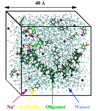
A few examples may serve as illustration. The following figure shows a simulation box containing water (represented by the blue triangles) as well as certain solute molecules. By using periodic boundaries the system becomes quasi infinite.
Figure 1 An example of a cube-shaped simulation volume filled with water (german: Wasser) and other molecules.
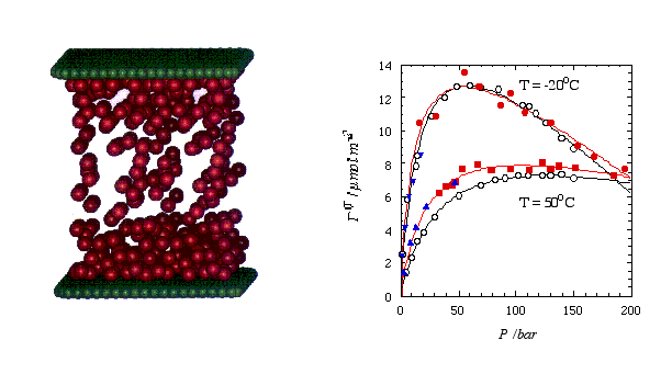
The picture below shows a snapshot (left) taken from a MD simulation of methane (red spheres) confined between two graphite surfaces (here graphically represented by two planar sheets of green carbon atoms). The system becomes quasi infinite by applying periodic boundary conditions parallel to the surfaces. The right panel shows the comparison of experimental (hollow symbols) and simulated adsorption isotherms. Here the surface excess methane is plotted vs. the methane bulk pressure. Note that the filled circles and the filled squares were obtained via MD, whereas MC was used at low pressures (triangles). For a simple system like this it probably is fair to say that the simulation is faster than the actual experiment.
Figure 2 Left: Snapshot taken from a MD simulation of methane (red spheres) confined between two parallel graphite surfaces (depicted by the green spheres; the actual surface potential includes the entire carbon half space). Right: Surface excess methane vs. bulk presssure at two temperatures. The open circles are experimental results (fitted by the black curves), whereas the solid symbols are simulated values (fitted by the red curves).
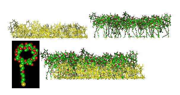
Figure 3 shows a simulation of the adsorption of a more complicated molecule, a cyclodextrin derivative (cf. the inset) on gold (surface not shown). In this case the simulation predicted a two-layer structure within the adsorbed monolayer (top: the two pseudo layers shown separately; bottom: actual monolayer). Both the packing density and the layer thickness were found within a few percent of the experimental result. Simulations of this type serve to understand the interaction of receptor-layers with guest molecules.
Figure 3 Simulation of a cyclodextrin derivative (inset) on gold. Separate representation (top) of the two layers which have formed during the adsorption of one monolayer (bottom) from solution. The gold substrate is omitted in this picture.
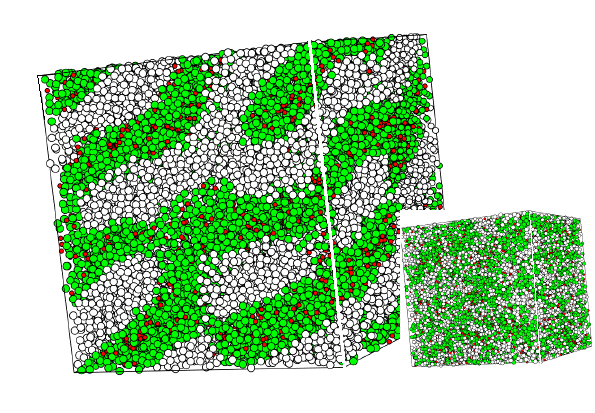
Figure 4 again shows a MD snapshot. Here the system contains 30000 interaction sites distributed over 3350 surfactant molecules (each consisting of four hydrophilic green and four hydrophobic white spheres) and 3200 water molecules (red spheres). The large picture shows the system close to equilibrium, whereas the inset shows the same system at the beginning of the simulation, when the surfactant distribution is random. Simulations of this type help to understand the formation of complex phase morphologies in surfactant systems.
Figure 4 MD-simulation of a system containing 30000 interaction sites (shown as spheres of different clor) corresponding to 3350 surfactant and 3200 water molecules. The picture shows a lamellar-type structure near equilibrium. The small system at the bottom right is the initial distribution of interaction sites.
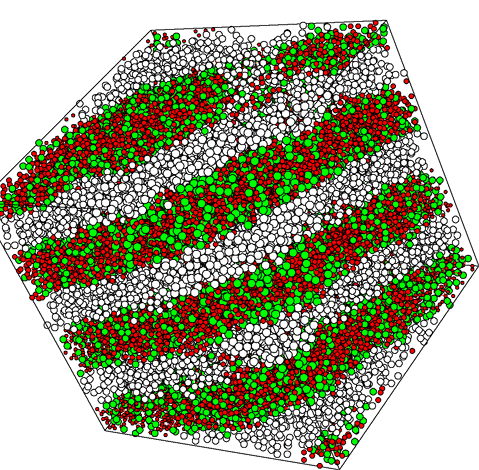
Figure 4a MD-Simulation as in figure 4 bit with additional water (red).
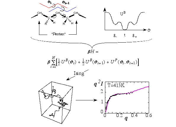
Figure 5 illustrates the path leading from the theoretical description of the conformation of a single polymer in terms of its backbone conformations, determined by the indicated torsion angles, to the test of the final model via the comparison to experimental scattering data (q is the magnitude of the momentum transfer, and I is the intensity; dots represent experimental points) obtain via neutron scattering from the melt. Here the transfer matrix method is used; an additional tool in the tool chest of molecular modelling. The Hamilton-function consists of potential energy terms describing isolated Butane-units, which couple via Pentane-terms. Based on this Ising-type model one may generate polymer conformations like the one shown (lower left). Calculating the average scattering intensity based on a large number of such conformations leads to the solid line shown in the lower right panel. These studies help to understand the relation between macromolecular structure and the properties of polymer materials.
Figure 5 Illustration of a series of steps which lead from the modeling of a chain-like polymer to the calculation of its scattering intensity in the melt.
